PC Controlled Vending Since
1994
Upstate Networks Incorporated
| PC Controlled Vending Since 1994 |
Upstate Networks Incorporated
|
| [ Home ] [ About ] [ Order ] [ Products ] [ Support ] [ News ] [ Customer Care ] [ Contact ] |
| New Zealand and Australian agent - Steward Electronics Ltd |
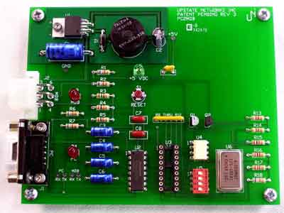
The PC2MDB™ PC2MDB allows the PC to act as a slave device for existing vending machine controllers (VMC). It allows the PC to act as a cashless device. The PC2MDB interfaces any MDB vending device to the PC via the serial port.. Perfect for PC interfaces to existing vending machines to allow the PC to control the vending machine. The PC2MDB™ is available in several different packages to meet the needs of developers and vending machine owners. Find out which package best meets your needs here The PC2MDB is a slave device for an already existing vending machine with a vending machine controller (VMC). It allows the PC to act as a cashless device and add credit(s) to the vending machine. Special versions allow the PC to act as a bill validator or coin acceptor/dispenser. By default the PC2MDB acts as device type 10 (cashless device) This describes the Interface Protocol for the PC2MDB Hardware circuit. The PC2MDB™ interfaces any MDB vending device (6-pin molex/5pin MTA) to the PC via the serial port (DB-9) Future support may include Universal Serial Bus. The PC2MDB™ protocol is compatible with standard RS-232 Protocol. For the most current PC2MDB User Guide please click here PC2MDB™ requires:
An IBM PC
compatible, with 486 or better processor.
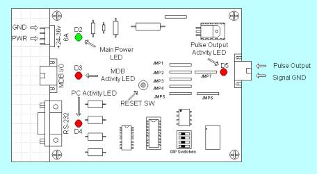
Table 1 – Dip Switch Functions
Table 2 - LED Functions
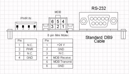
Power requirements Pin 8 CTS Figure-2 Connector Pin OutsInstall the PC2MDB™It is time to install the PC2MDB™ itself and move on to the testing phase. Installation is relatively simple; there are only three connections that must be made for full functioning of the device. There are connectors on the edge of the board. One cable plugs into a 24VDC power supply. The 6-pin Molex connects to the VMC. The final connector is a DB-9 and connects into the back of the computer. There should be an open port on the back of the computer labeled “SERIAL2” or “COM2.” SoftwareOverviewWhen the master/VMC has data to send we check the mode bit to differentiate between ADDRESS bytes and DATA bytes. The upper five bits (MSB) of the Address Byte are used for addressing. The lower three bits of the Address Byte contain peripheral specific commands. This will allow up to eight instructions to be embedded in the first byte of block.
The PC2MDB sends information generated by the VMC device directly to the PC via RS-232 serial communication. It responds to polls issued by the VMC. PC2MDB will ACK only the polls, and commands issued to correct addresses. The PC2MDB then forwards the commands to the PC. Once the data has been processed, the PC sends back another set of instructions to the PC2MDB, which forwards these instructions to the VMC only when desired poll/polls have been received. The information sent to the PC is send as bytes in hexadecimal. The first byte sent is the device ID. For example 30 XX means that a bill validator has sent information. Whereas 08 XX means that a coin mechanism has sent data. Consult your manual for commands specific to your MDB device. We have included command sets for various MDB devices in this document. Please note that all examples of source code are written in MS Visual Basic 5.0
MDB2PC Software Communication
ReceiveUse an interrupt driven comm event on the appropriate port. Settings are 9600-8-1-None. Set the receive threshold to 1. Empty the contents of the receive buffer as soon as there is at least one character ready. See the sample source code provided on CD-ROM for an example. ************************************************************************************************ Case comEvReceive 'Received RThreshold # of Chars Do While comm_port.InBufferCount > 0 MDB2PC XE "MDB2PC" _input$ = comm_port.Input ‘ MDB2PC XE "MDB2PC" _input$ is the output of the MDB XE "MDB" to the PC looking at the first five ‘characters of MDB2PC XE "MDB2PC" _input$ ‘enables the PC to determine current action of the MDB XE "MDB" . To look at the first five ‘characters of MDB2PC XE "MDB2PC" _input$, use Mid$(MDB2PC_input$, 1, 2)
b$ = Mid$(MDB2PC XE "MDB2PC" _input$, 1, 5) ' shorthand for looking at the first 5 characters 'The following are the typical actions produced by the MDB XE "MDB" If b$ = Mid$(MDB2PC XE "MDB2PC" _input$, 1, 2) = 50 Then Label3.Caption = "Nickel received" nickins = nickins + 1 RXSum = RXSum + 0.05 End If *********************************************************************** TransmitUse an interrupt driven comm event on the appropriate port. Settings are 9600-8-1-None. Set the transmit threshold to 1. Send the address of the device followed by the command parameters. *********************************************************************** Private Sub Command6_Click() MDB_output_string = Chr$(13) & Chr$(&H52) 'Dispense XE "Dispense" Quarter comm_port.DTREnable = True ‘Start Handshaking XE "Handshaking" End Sub Case comEvCTS 'Change in the CTS line ' this is the output routine for transmitting ' outbuffersize set to 32 bytes, SThreshold = 1 comm_port.Output = MDB XE "MDB" _output_string comm_port.DTREnable = False 'END transmit one character on change of CTS line ***********************************************************************
Handshaking XE "Handshaking"When the PC has data to send to a slave device the following is required for sending this data:
Notes: Place the string to be transmitted in a temporary variable and then place the temporary variable in the output buffer. For example (2): Private Sub cmdDispenseNickel_Click() On Error GoTo ErrorHandler ' Dispense a Nickel MDB_output_string = Chr$(13) & Chr$(&H10) comInterface.DTREnable = True ' Update the Activity Log lstActionLog.AddItem "Dispense Nickel" Exit Sub ErrorHandler: Resume Next End Sub Since we have the contents to be transmitted in a temporary string (MDB_output_string) and we ‘have set DTR high (comInterface.DTREnable = True) we now wait for a comm. Event to be generated ‘namely a change in the CTS line For Example(2&3): Case
comEvCTS 'Change
in the CTS line ‘At this point the data has been sent to the output buffer of the serial port UART. By setting ‘the Send Threshold to 1 we fire a comm. Send event when the entire contents of the output buffer ‘have been sent and set DTR low to indicate that we have completed transmission. For example(4) Case comEvSend
'There are SThreshold number of characters in
thetransmit buffer ‘****************************************************************
|
||||||||||||||||||||||||||||||||||||||||||||||||||||||||||||||||
[ Home
] [ About
] [ Order
] [ Products
] [ Support ]
[ News
] [ Customer
Care ] [ Contact ]
| ©Copyright 2008 Upstate Networks Inc.
All Rights Reserved For more information Contact Us The CashCube™, MDB2PC, BA2PC, and MDB2USB are trademarks of Upstate Networks, Inc. Other product names and various content (including but not limited to audio, video, and graphics) are trademarks of Upstate Networks. |